rfid em 18 reader module pin diagram EM18 RFID Reader is a module which reads the ID information stored in RFID . Fans can catch every game of the 2024 Auburn football season on WGZZ 94.3 FM, the Tigers' flagship station. You can also listen to Auburn football games with a SiriusXM .
0 · rfid module datasheet
1 · em18 with arduino
2 · em18 rfid reader price
3 · em18 rfid reader pinout
4 · em18 rfid reader datasheet
5 · em 18 reader module pinout
6 · em 18 reader module datasheet
7 · em 18 full form
หลังจากที่ผมไปอัพ 4.2.2 ที่ร้านมา xz ของผมเวลาเปิด NFC แล้วมันไม่ขึ้นที่แถบข้างบนอะครับ ต้องแก้ยังไง
EM18 RFID Reader is a module which reads the ID information stored in RFID .EM18 is a RFID reader which is used to read RFID tags of frequency 125 kHz. After reading .
This article describes the construction of a simple Arduino RFID Access control . EM-18 RFID Module. This tutorial will show you how to quickly setup and start .(RFID tags) Em-18 Pin Configuration. The EM-18 bears a nine-pin configuration whereby seven .Learn how to use the EM-18 RFID reader module with detailed documentation, including .
In this tutorial we will learn How to interface EM-18 RFID Reader Module with .
As we know EM-18 gives two methods to get output (RS-232 and Weigand). So wisely choose .
RFID Interfacing With PIC16F877A Component Required. EM18 Module; LCD . EM18 RFID Reader is a module which reads the ID information stored in RFID TAGS. This ID information is unique for every TAG which cannot be copied. EM-18 Pin Configuration. EM-18 is a nine pin device. Among nine pins, 2 pins are not connected, so we basically have to consider seven terminals. In this tutorial, we will Interface with the EM-18 RFID module using Arduino Nano, ESP8266, and ESP32 board.
EM18 is a RFID reader which is used to read RFID tags of frequency 125 kHz. After reading tags, it transmits unique ID serially to the PC or microcontroller using UART communication or Wiegand format on respective pins. This article describes the construction of a simple Arduino RFID Access control DIY (Do It Yourself) Project using Arduino UNO and a RFID reader module (EM-18) to control an LED and a Relay. Circuit schematic and Arduino Sketch (source code) are provided here.
EM-18 RFID Module. This tutorial will show you how to quickly setup and start using the EM-18 RFID Module. Before continuing with this tutorial, watch the demo video to get a better understanding of how the product works, and then try it yourself! What you .
(RFID tags) Em-18 Pin Configuration. The EM-18 bears a nine-pin configuration whereby seven of the pins are connected, and two aren’t. Below is a table of the em-18 design.Learn how to use the EM-18 RFID reader module with detailed documentation, including pinouts, usage guides, and example projects. Perfect for students, hobbyists, and developers integrating the EM-18 RFID reader module into their circuits.
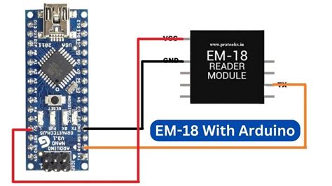
In this tutorial we will learn How to interface EM-18 RFID Reader Module with Arduino Uno. Connect the TX of RFID Reader to RX of Arduino for communication.As we know EM-18 gives two methods to get output (RS-232 and Weigand). So wisely choose a SELECT pin. A high Select pin will enable RS 232 output and Low SELECT pin will enable Weigand output.
RFID Interfacing With PIC16F877A Component Required. EM18 Module; LCD Module; PIC16F877A Development Board; Circuit Diagram. The full circuit diagram for interfacing the RFID module to PIC16F877A is shown below. The unique ID code in the RFID card is read by the circuit and displayed on the 16×2 LCD display. LCD: EM18 RFID Reader is a module which reads the ID information stored in RFID TAGS. This ID information is unique for every TAG which cannot be copied. EM-18 Pin Configuration. EM-18 is a nine pin device. Among nine pins, 2 pins are not connected, so we basically have to consider seven terminals.
rfid module datasheet
In this tutorial, we will Interface with the EM-18 RFID module using Arduino Nano, ESP8266, and ESP32 board.EM18 is a RFID reader which is used to read RFID tags of frequency 125 kHz. After reading tags, it transmits unique ID serially to the PC or microcontroller using UART communication or Wiegand format on respective pins. This article describes the construction of a simple Arduino RFID Access control DIY (Do It Yourself) Project using Arduino UNO and a RFID reader module (EM-18) to control an LED and a Relay. Circuit schematic and Arduino Sketch (source code) are provided here. EM-18 RFID Module. This tutorial will show you how to quickly setup and start using the EM-18 RFID Module. Before continuing with this tutorial, watch the demo video to get a better understanding of how the product works, and then try it yourself! What you .
(RFID tags) Em-18 Pin Configuration. The EM-18 bears a nine-pin configuration whereby seven of the pins are connected, and two aren’t. Below is a table of the em-18 design.Learn how to use the EM-18 RFID reader module with detailed documentation, including pinouts, usage guides, and example projects. Perfect for students, hobbyists, and developers integrating the EM-18 RFID reader module into their circuits. In this tutorial we will learn How to interface EM-18 RFID Reader Module with Arduino Uno. Connect the TX of RFID Reader to RX of Arduino for communication.As we know EM-18 gives two methods to get output (RS-232 and Weigand). So wisely choose a SELECT pin. A high Select pin will enable RS 232 output and Low SELECT pin will enable Weigand output.

do passports have rfid protection
pop sonic pop up wallet with rfid protection

List via AuburnTigers.com of radio stations across the South that air Auburn football games.. Auburn Football Radio Affiliates {}Abbeville WESZ-FM 98.7 {}Greenville .Statewide coverage is the hallmark of the Auburn Sports Network's exclusive coverage of Auburn football. All home and away games are broadcast across the entire state .
rfid em 18 reader module pin diagram|em18 with arduino