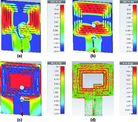
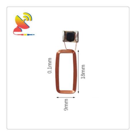
rfid reader antenna design 13.56mhz This method is based on eDesignSuite, a free on-line tool (available on www.st.com) featuring a calculation module that helps customers to design single-layer, rectangular coil antennas for NFC applications. Antenna tuning frequency adjustment and . Hardware NFC Reader using adruino for old 3ds. Eridion kiorai; Jan 1, 2024; .
0 · 13.56mhz antenna diagram
1 · 13.56 mhz rfid antenna
2 · 13.56 mhz antenna design
3 · 13.56 inch antenna design
4 · 13.56 frequency rfid
The ST25RU3993 RAIN ® (UHF) RFID reader device provides multi-protocol support for the 840-960 MHz UHF band compatible with ISO18000-62 & -63, ISO29143 and to GS1’s EPC UHF Gen2 air interface protocol.
How to design a 13.56 MHz customized antenna for ST25 NFC / RFID Tags. Introduction. The ST25 NFC (near field communication) and RFID (radio frequency identification) tags extract .This method is based on eDesignSuite, a free on-line tool (available on www.st.com) featuring a calculation module that helps customers to design single-layer, rectangular coil antennas for .How to design a 13.56 MHz customized antenna for ST25 NFC / RFID Tags. Introduction. The ST25 NFC (near field communication) and RFID (radio frequency identification) tags extract their power from the reader field. The tag and reader antennas are inductances mutually coupled by the magnetic field, similarly to a voltage transformer (see Figure 1).
This method is based on eDesignSuite, a free on-line tool (available on www.st.com) featuring a calculation module that helps customers to design single-layer, rectangular coil antennas for NFC applications. Antenna tuning frequency adjustment and .
This document is aimed at providing 13.56 MHz RFID systems designers with a practical cookbook on how to optimize RFID systems and antennas. A thorough analysis of the most important RFID system parameters is presented. The emphasis is placed on physical concepts, rather than on lengthy theoretical calculations. 2 Antenna ? You said Antenna ?Since RFID technology is developed, 13.56 MHz RFID system with its excellent performance is widely applied. 13.56MHz RFID system is a passive system. So the performance of the antenna directly affects the performance of the RFID system.This paper describes the design steps for creating and tuning an NFC/high frequency (HF) RFID antenna tuned to 13.56 MHz for the TRF79xxA series of devices. The matching network uses a 50-Ω 3-element match. A 3-element match is recommended as it allows the designer to select the required antenna quality factor (Q) for the application. Contents.
The presented article describes the development of efficient HF antennas for use in RFID systems operating at 13.56 MHz. Various features and requirements of antennas were discussed and linked to key design parameters such as antenna form-factor and size; RF power level, materials and communication protocol.This document gives an overview of how to evaluate the electrical characteristics of mass-produced 13.56 MHz RFID tags and readers/ writers and their components. For engineers who work in RFID antenna test, this note discusses 13.56 MHz RFID antenna testing and designing with network and impedance analyzers.Unfortunately, it is not easy to design a good 13.56 MHz antenna. In general, a good antenna is at least 1/4 of the operating wavelength (of ~22m), so any practical 13.56 MHz antenna would be a bad antenna.How to design a 13.56 MHz customized tag antenna. Introduction. RFID (radio-frequency identification) tags extract all of their power from the reader’s field. The tags’ and reader’s antennas form a system of coupled inductances as shown in Figure 1. The loop antenna of the tag acts as a transformer’s secondary.
13.56 mhz reader reference design for the mcrf450/451/452/455 read/write devices AND MCRF355/360 READ-ONLY DEVICES 1.0 Introduction..........................................163
13.56mhz antenna diagram

How to design a 13.56 MHz customized antenna for ST25 NFC / RFID Tags. Introduction. The ST25 NFC (near field communication) and RFID (radio frequency identification) tags extract their power from the reader field. The tag and reader antennas are inductances mutually coupled by the magnetic field, similarly to a voltage transformer (see Figure 1).This method is based on eDesignSuite, a free on-line tool (available on www.st.com) featuring a calculation module that helps customers to design single-layer, rectangular coil antennas for NFC applications. Antenna tuning frequency adjustment and .
nfc tag samsung note 10
This document is aimed at providing 13.56 MHz RFID systems designers with a practical cookbook on how to optimize RFID systems and antennas. A thorough analysis of the most important RFID system parameters is presented. The emphasis is placed on physical concepts, rather than on lengthy theoretical calculations. 2 Antenna ? You said Antenna ?Since RFID technology is developed, 13.56 MHz RFID system with its excellent performance is widely applied. 13.56MHz RFID system is a passive system. So the performance of the antenna directly affects the performance of the RFID system.This paper describes the design steps for creating and tuning an NFC/high frequency (HF) RFID antenna tuned to 13.56 MHz for the TRF79xxA series of devices. The matching network uses a 50-Ω 3-element match. A 3-element match is recommended as it allows the designer to select the required antenna quality factor (Q) for the application. Contents.
The presented article describes the development of efficient HF antennas for use in RFID systems operating at 13.56 MHz. Various features and requirements of antennas were discussed and linked to key design parameters such as antenna form-factor and size; RF power level, materials and communication protocol.This document gives an overview of how to evaluate the electrical characteristics of mass-produced 13.56 MHz RFID tags and readers/ writers and their components. For engineers who work in RFID antenna test, this note discusses 13.56 MHz RFID antenna testing and designing with network and impedance analyzers.Unfortunately, it is not easy to design a good 13.56 MHz antenna. In general, a good antenna is at least 1/4 of the operating wavelength (of ~22m), so any practical 13.56 MHz antenna would be a bad antenna.
13.56 mhz rfid antenna
How to design a 13.56 MHz customized tag antenna. Introduction. RFID (radio-frequency identification) tags extract all of their power from the reader’s field. The tags’ and reader’s antennas form a system of coupled inductances as shown in Figure 1. The loop antenna of the tag acts as a transformer’s secondary.

13.56 mhz antenna design


nfc tag not supported samsung a5 2017
nfc tag sticker buy
Step 1. Using two fingers, swipe down from the top of the screen to open the Quick settings panel. Tap More options (the three vertical dots) > Edit buttons. Step 2. Touch and hold the NFC icon, and then drag and drop it into .
rfid reader antenna design 13.56mhz|13.56mhz antenna diagram