em18 rfid reader module datasheet pdf microcontrollers using UART communication. The EM-18 RFID Reader module generates and . Green Bay Packers 6-3 (third place, NFC North): The Packers, after a Week 10 bye, need to get back on track to strengthen their wild-card position by beating the Bears in .
0 · em18 with arduino
1 · em18 rfid reader price
2 · em18 rfid reader datasheet
3 · em 18 rfid reader module
4 · em 18 reader module datasheet
5 · em 18 reader module
6 · em 18 pin diagram
7 · em 18 full form
A simple way to check if your credit card has RFID technology is to visually .

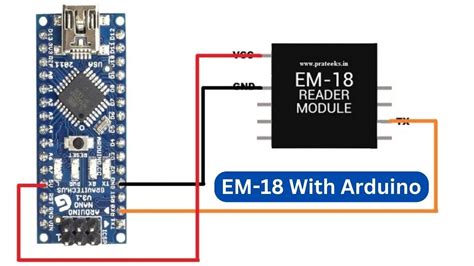
em18 with arduino
EM18 RFID Reader is a module which reads the ID information stored in RFID .The EM-18 RFID Reader module operating at 125kHz is an inexpensive solution for your RFI.The EM-18 RFID Reader module operating at 125kHz is an inexpensive solution for your RFID . If you need an inexpensive way to get started with RFID, this is a great little .
microcontrollers using UART communication. The EM-18 RFID Reader module generates and . In this tutorial, we will Interface with the EM-18 RFID module using Arduino . EM-18 RFID reader is one of the commonly used RFID readers to read 125KHz .
Equipped with powerful antennas, the EM 18 RFID reader has the impressive capability to read . This article describes the construction of a simple Arduino RFID Access control .This RFID Reader Module works with any 125 KHz RFID tags . Specifications : 5VDC through . EM18 RFID Reader is a module which reads the ID information stored in RFID TAGS. This ID information is unique for every TAG which cannot be copied. EM-18 Pin Configuration. EM-18 is a nine pin device. Among nine pins, 2 pins are not connected, so we basically have to consider seven terminals.
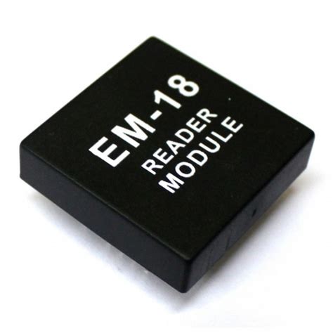
The EM-18 RFID Reader module operating at 125kHz is an inexpensive solution for your RFID based application. The Reader module comes with an on-chip antenna and can be powered up with a 5V power supply. If you need an inexpensive way to get started with RFID, this is a great little module. Just power the module, and it will read any RFID card within range. It will output the card’s ID in a serial string, which can easily be read by any microcontroller.EM18 is a RFID reader which is used to read RFID tags of frequency 125 kHz. After reading tags, it transmits unique ID serially to the PC or microcontroller using UART communication or Wiegand format on respective pins.
microcontrollers using UART communication. The EM-18 RFID Reader module generates and radiates RF Carrier Signals of frequency 125 KHz through its coils. When a 125 KHz passive RFID Tag is brought in to this field, will get energized from it. FEATURES: Working frequency: 125khz Working Voltage: DC 3.3V - 5V Working Current: 19mA - 25mA In this tutorial, we will Interface with the EM-18 RFID module using Arduino Nano, ESP8266, and ESP32 board.
EM-18 RFID reader is one of the commonly used RFID readers to read 125KHz tags. It features low cost, low power consumption, small form factor, and easy to use. It provides both UART and Wiegand26 output formats.
Equipped with powerful antennas, the EM 18 RFID reader has the impressive capability to read tags from a considerable distance, eliminating the need for physical contact or line of sight. The intelligence embedded within the EM 18 RFID reader is truly commendable.

This article describes the construction of a simple Arduino RFID Access control DIY (Do It Yourself) Project using Arduino UNO and a RFID reader module (EM-18) to control an LED and a Relay. Circuit schematic and Arduino Sketch (source code) are provided here.
This RFID Reader Module works with any 125 KHz RFID tags . Specifications : 5VDC through USB (External 5V supply will boost range of the module) Current: <50mA; Operating Frequency: 125Khz; Read Distance: 10cm; Size of RFID reader module: 32mm(length) * 32mm(width) * 8mm(height) Pin Configuration of EM-18 Reader Module is shown in the figure:. EM18 RFID Reader is a module which reads the ID information stored in RFID TAGS. This ID information is unique for every TAG which cannot be copied. EM-18 Pin Configuration. EM-18 is a nine pin device. Among nine pins, 2 pins are not connected, so we basically have to consider seven terminals.The EM-18 RFID Reader module operating at 125kHz is an inexpensive solution for your RFID based application. The Reader module comes with an on-chip antenna and can be powered up with a 5V power supply. If you need an inexpensive way to get started with RFID, this is a great little module. Just power the module, and it will read any RFID card within range. It will output the card’s ID in a serial string, which can easily be read by any microcontroller.
EM18 is a RFID reader which is used to read RFID tags of frequency 125 kHz. After reading tags, it transmits unique ID serially to the PC or microcontroller using UART communication or Wiegand format on respective pins.
em18 rfid reader price
microcontrollers using UART communication. The EM-18 RFID Reader module generates and radiates RF Carrier Signals of frequency 125 KHz through its coils. When a 125 KHz passive RFID Tag is brought in to this field, will get energized from it. FEATURES: Working frequency: 125khz Working Voltage: DC 3.3V - 5V Working Current: 19mA - 25mA In this tutorial, we will Interface with the EM-18 RFID module using Arduino Nano, ESP8266, and ESP32 board.
EM-18 RFID reader is one of the commonly used RFID readers to read 125KHz tags. It features low cost, low power consumption, small form factor, and easy to use. It provides both UART and Wiegand26 output formats.Equipped with powerful antennas, the EM 18 RFID reader has the impressive capability to read tags from a considerable distance, eliminating the need for physical contact or line of sight. The intelligence embedded within the EM 18 RFID reader is truly commendable. This article describes the construction of a simple Arduino RFID Access control DIY (Do It Yourself) Project using Arduino UNO and a RFID reader module (EM-18) to control an LED and a Relay. Circuit schematic and Arduino Sketch (source code) are provided here.

rfid readers for marijuana industry
Memory Calculations. Each NFC chip's memory is divided into two sections - user memory and system memory. So, while an NTAG210 has 80 bytes of memory, only 48 bytes of memory is actually available to be encoded. To .
em18 rfid reader module datasheet pdf|em 18 reader module