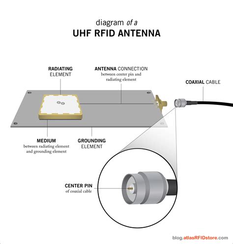
rfid chip schematic Radio Frequency Identification (RFID) systems use radio frequency to identify, locate and track people, assets and animals. Passive RFID systems are composed of three components – a . Get the #1 digital business card for corporate customers. Share contact .
0 · rfid antenna size chart
1 · rfid antenna circuit size
2 · rfid antenna circuit diagram
3 · rfid antenna circuit design
4 · rfid 125khz
5 · microid rfid circuit diagram
6 · microid 13.56 rfid circuit
7 · microid 125 rfid system
Score new characters, game modes, or other perks in compatible games with amiibo™ accessories! amiibo for Nintendo Switch, Wii U, and New Nintendo 3DS XL.
rfid antenna size chart
This section is written for RF coil designers and RFID system engineers. It reviews basic electromagnetic theories on antenna coils, a procedure for coil design, calculation and .Radio Frequency Identification (RFID) systems use radio frequency to identify, locate and track people, assets and animals. Passive RFID systems are composed of three components – a .
rfid antenna circuit size
Radio Frequency Identification (RFID) systems use radio frequency to identify, locate and track people, assets and animals. Passive RFID systems are composed of three components – a reader (interroga-tor), passive tag and host computer. The tag is com-posed of an antenna coil and a silicon chip that includes basic modulation circuitry and non .
This section is written for RF coil designers and RFID system engineers. It reviews basic electromagnetic theories on antenna coils, a procedure for coil design, calculation and measurement of inductance, an antenna tuning method, and read range in RFID applications. 2003 Microchip Technology Inc.
Radio Frequency Identification (RFID) systems use radio frequency to identify, locate and track people, assets and animals. Passive RFID systems are composed of three components – a reader (interroga-tor), passive tag and host computer. The tag is composed of an antenna coil and a silicon chip that includes basic modulation circuitry and .
This Radio Frequency Identification (RFID) reference design outlines the required components, layout considerations, and provides firmware examples to implement RFID into applications for extracting RFID data from transponders. RFID enables access .
RFID Block Schematic: A simplified block schematic of an RFID tag (also called transponder) is shown in the diagram below. Various components of the tag are as shown. Normally, the antenna is external to the tag chip, and large in size. PN532 (https://adafru.it/eHi). The Adafruit PN532 library has the ability to read MiFare cards, including the hard-coded ID numbers, as well as authenticate and read/write EEPROM chunks. It can work with both the breakout and .
Learn the different components that go into an RFID Tag such as RFID chip, inlay, antenna and strap. Choosing the best RFID is important for any RFID project.
rfid antenna circuit diagram
When looking into implementing a passive RFID tag system into your business, one of the most important diagrams to have is the passive RFID tag schematic diagram. This diagram will show you the components that make up an RFID tag and how they work together. The RFID chip system architecture is designed to carry and transmit a unique identification seamlessly by integrating three essential components: the RF Transceiver, Detection Section, and Control Section.The design stage involves creating a schematic diagram of the RFID PCB. This diagram includes all the necessary components, such as the RFID chip, antenna, and other supporting components.Radio Frequency Identification (RFID) systems use radio frequency to identify, locate and track people, assets and animals. Passive RFID systems are composed of three components – a reader (interroga-tor), passive tag and host computer. The tag is com-posed of an antenna coil and a silicon chip that includes basic modulation circuitry and non .

This section is written for RF coil designers and RFID system engineers. It reviews basic electromagnetic theories on antenna coils, a procedure for coil design, calculation and measurement of inductance, an antenna tuning method, and read range in RFID applications. 2003 Microchip Technology Inc.Radio Frequency Identification (RFID) systems use radio frequency to identify, locate and track people, assets and animals. Passive RFID systems are composed of three components – a reader (interroga-tor), passive tag and host computer. The tag is composed of an antenna coil and a silicon chip that includes basic modulation circuitry and .This Radio Frequency Identification (RFID) reference design outlines the required components, layout considerations, and provides firmware examples to implement RFID into applications for extracting RFID data from transponders. RFID enables access .
RFID Block Schematic: A simplified block schematic of an RFID tag (also called transponder) is shown in the diagram below. Various components of the tag are as shown. Normally, the antenna is external to the tag chip, and large in size.
PN532 (https://adafru.it/eHi). The Adafruit PN532 library has the ability to read MiFare cards, including the hard-coded ID numbers, as well as authenticate and read/write EEPROM chunks. It can work with both the breakout and .
Learn the different components that go into an RFID Tag such as RFID chip, inlay, antenna and strap. Choosing the best RFID is important for any RFID project. When looking into implementing a passive RFID tag system into your business, one of the most important diagrams to have is the passive RFID tag schematic diagram. This diagram will show you the components that make up an RFID tag and how they work together. The RFID chip system architecture is designed to carry and transmit a unique identification seamlessly by integrating three essential components: the RF Transceiver, Detection Section, and Control Section.
rfid based attendance system using arduino uno pdf

rfid antenna circuit design
rfid 125khz
microid rfid circuit diagram
Get the latest 2024 NFL Playoff Picture seeds and scenarios. See the full NFL conference standings and wild card teams as if the season ended today.
rfid chip schematic|rfid antenna circuit size