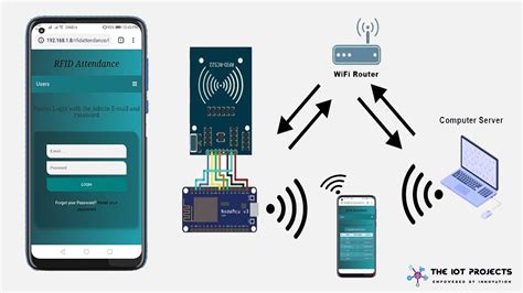
rfid based attendance system circuit diagram This is a simple RFID based attendance system circuit diagram using ATmega8 Microcontroller and working process, source code. Visit the official source for NFL News, NFL schedules, stats, scores and more. Get .
0 · rfid based attendance system using nodemcu
1 · rfid based attendance system using 8051
2 · rfid based attendance system pdf
3 · rfid attendance tracking system
4 · rfid attendance system using esp32
5 · rfid attendance system using atmega32
6 · rfid attendance system pdf
7 · attendance monitoring system using rfid
See the latest NFL Standings by Division, Conference and League. Find current or .
Here we will count the attendance of an authorized person by using RFID. We can divide the complete attendance system into different sections: reader section, control section, .
This is a simple RFID based attendance system circuit diagram using ATmega8 Microcontroller and working process, source code. Here we will count the attendance of an authorized person by using RFID. We can divide the complete attendance system into different sections: reader section, control section, driver section and display section. Role of each section is shown in the below block diagram: Reader Section. This is a simple RFID based attendance system circuit diagram using ATmega8 Microcontroller and working process, source code.
So, In this project we have designed RFID Based Attendance System using Arduino and RFID MFRC522 Module. In this system, each student is issued an RFID card as their id card and their attendance is marked when they touch their card to .
Learn how you can make your own RFID based attendance system using Arduino and display the status of attendance on a 16x2 LCD. This is the block diagram of our project RFID Based Attendance System using Arduino, RTC & LCD Display. Here Arduino UNO acts as a central processor for controlling all other components as input/output unit. Circuit Diagram. Source Code. Demo Of Projects. Video Tutorial. Introduction. In this project, we are going to build an RFID-based attendance system using Arduino nano. The RFID-based attendance system is a very interesting project which can be used in different places like Schools, colleges And Companies.

Circuit Diagram. The complete circuit diagrams for the RFID Smart Attendance system is shown below. The Circuit Diagram was created using Fritzing software. The connection between Arduino and RFID are shown in below table: Circuit Diagram – RFID based Attendance System. Project Description. The full circuit diagram for interfacing RFID module to Arduino is shown above. The unique ID code in the RFID card is read by the circuit and the name of the corresponding person will be displayed on the 20 x 4 LCD display.
Here we will discuss the Introduction to RFID Based Attendance System with Database Management using Arduino, Project Concept, Block Diagram, Components Required, Circuit Diagram, Working Principle, and Arduino code.
RFID RC522 Based Attendance System Using Arduino with Data Logger. Interface MFRC522 with Arduino UNO Board, 16x2 LCD, SD Card Module and DS3231 RTC Module. Here we will count the attendance of an authorized person by using RFID. We can divide the complete attendance system into different sections: reader section, control section, driver section and display section. Role of each section is shown in the below block diagram: Reader Section. This is a simple RFID based attendance system circuit diagram using ATmega8 Microcontroller and working process, source code. So, In this project we have designed RFID Based Attendance System using Arduino and RFID MFRC522 Module. In this system, each student is issued an RFID card as their id card and their attendance is marked when they touch their card to .
Learn how you can make your own RFID based attendance system using Arduino and display the status of attendance on a 16x2 LCD.
rfid based attendance system using nodemcu
This is the block diagram of our project RFID Based Attendance System using Arduino, RTC & LCD Display. Here Arduino UNO acts as a central processor for controlling all other components as input/output unit.
Circuit Diagram. Source Code. Demo Of Projects. Video Tutorial. Introduction. In this project, we are going to build an RFID-based attendance system using Arduino nano. The RFID-based attendance system is a very interesting project which can be used in different places like Schools, colleges And Companies. Circuit Diagram. The complete circuit diagrams for the RFID Smart Attendance system is shown below. The Circuit Diagram was created using Fritzing software. The connection between Arduino and RFID are shown in below table: Circuit Diagram – RFID based Attendance System. Project Description. The full circuit diagram for interfacing RFID module to Arduino is shown above. The unique ID code in the RFID card is read by the circuit and the name of the corresponding person will be displayed on the 20 x 4 LCD display.
Here we will discuss the Introduction to RFID Based Attendance System with Database Management using Arduino, Project Concept, Block Diagram, Components Required, Circuit Diagram, Working Principle, and Arduino code.
rfid based attendance system using 8051
Complete coverage of the 2023 NFL Playoffs including a schedule, game times, and bracket for AFC and NFC playoff games. Get the latest updates from CBS Sports on the road to Super .View the NFL Playoff Schedule for the 2023-2024 football season at FBSchedules.com. The schedule includes matchups, date, time, and TV. . AFC/NFC Wild-Card Round . NFC .
rfid based attendance system circuit diagram|rfid attendance system pdf