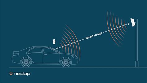
modulation to increase snr of rfid tag When designing for optimum read range, you should primarily consider the reader's power, the tag's power consumption, the tag's quality factor (Q), the tag's tuning, the reader's antenna aperture, and the tag's antenna aperture.
Free Credit icons, logos, symbols in 50+ UI design styles. Download Static and .
0 · rfid reading volume
1 · rfid reading range
MoreRFID, is one of the leading IC Card manufacturers in China, we supply IC .
One obvious way to increase the received SNR is to increase the bit duration, i.e. lower the tag bitrate Rb = 1/Tb. On the other hand, for a given tag bitrate, control over Γ0, Γ1 is needed to increase the SNR at the reader by maximizing |∆Γ|.An RFID tag must accomplish the EEPROM interface using just one signal path (a). A typical RFID IC encompasses a significant array of functional blocks plus power-recovery functions (b).Then, we show how a manufacturer can improve a tag’s decoding ability (and thus its range) by using a lower data transmission rate. This is because a low data rate improves the signal-to-noise ratio (SNR) of the communication paths of both the reader-to-tag and the tag-to-reader.For the purpose of achieving high SNR for radio frequency identification (RFID) communication systems, Barker codes, a binary phase shift keying (BPSK) modulation technique, have been adopted in this study. Passive SAW RFID tags were designed with 5-bit Barker code sequences to generate BPSK modulated signals.
PIGGYBACK MODULATION. In a passive tag, ASIC (application specific integrated circuit) of the tag switches its input impedance between two states to modulate the RCS (radar cross section) of the tag antenna.
When designing for optimum read range, you should primarily consider the reader's power, the tag's power consumption, the tag's quality factor (Q), the tag's tuning, the reader's antenna aperture, and the tag's antenna aperture.modulation and detection range improvement and has given improved performance in detecting tag at a comparatively longer distance in outdoor non line of sight (NLOS) . RFID tags, on the other hand, have no internal power supply and, therefore, can be much smaller and have an unlimited life span [3]. Passive tags can themselves be classified as
The majority of state-of-the-art fine-grained RFID localiza-tion relies on a technique called dual-frequency excitation [3]. This technique allows systems to perform accurate time-of-flight estimation by collecting ultra-wideband (UWB) channel measurements from .To overcome this weakness, we propose a new transmission scheme to increase the data rate of a tag without degrading the demodulation performance or requiring additional battery power. In this paper, we present two-dimensional bi-orthogonal signaling and orthogonal multiplexing techniques for passive RFID tags.
rfid reading volume
In this paper, our goal is to increase the RFID read rates for different modulation schemes at various Signal to Noise Ratios (SNRs). We propose and evaluate a selected subset of improvements, which can be implemented purely on the reader side and conform to the standard.One obvious way to increase the received SNR is to increase the bit duration, i.e. lower the tag bitrate Rb = 1/Tb. On the other hand, for a given tag bitrate, control over Γ0, Γ1 is needed to increase the SNR at the reader by maximizing |∆Γ|.An RFID tag must accomplish the EEPROM interface using just one signal path (a). A typical RFID IC encompasses a significant array of functional blocks plus power-recovery functions (b).
Then, we show how a manufacturer can improve a tag’s decoding ability (and thus its range) by using a lower data transmission rate. This is because a low data rate improves the signal-to-noise ratio (SNR) of the communication paths of both the reader-to-tag and the tag-to-reader.
For the purpose of achieving high SNR for radio frequency identification (RFID) communication systems, Barker codes, a binary phase shift keying (BPSK) modulation technique, have been adopted in this study. Passive SAW RFID tags were designed with 5-bit Barker code sequences to generate BPSK modulated signals.

PIGGYBACK MODULATION. In a passive tag, ASIC (application specific integrated circuit) of the tag switches its input impedance between two states to modulate the RCS (radar cross section) of the tag antenna. When designing for optimum read range, you should primarily consider the reader's power, the tag's power consumption, the tag's quality factor (Q), the tag's tuning, the reader's antenna aperture, and the tag's antenna aperture.modulation and detection range improvement and has given improved performance in detecting tag at a comparatively longer distance in outdoor non line of sight (NLOS) . RFID tags, on the other hand, have no internal power supply and, therefore, can be much smaller and have an unlimited life span [3]. Passive tags can themselves be classified asThe majority of state-of-the-art fine-grained RFID localiza-tion relies on a technique called dual-frequency excitation [3]. This technique allows systems to perform accurate time-of-flight estimation by collecting ultra-wideband (UWB) channel measurements from .
To overcome this weakness, we propose a new transmission scheme to increase the data rate of a tag without degrading the demodulation performance or requiring additional battery power. In this paper, we present two-dimensional bi-orthogonal signaling and orthogonal multiplexing techniques for passive RFID tags.
nfl standings and records

2022 afc north standings
TAP AND RIDE: LA Metro users can now use their Android NFC phone to make contactless fare payments Passengers on public transportation services in the US city of Los Angeles can now add their TAP transit card to .
modulation to increase snr of rfid tag|rfid reading range