rfid reader antenna design This section is written for RF coil designers and RFID system engineers. It reviews basic electromagnetic theories on antenna coils, a procedure for coil design, calculation and measurement of inductance, an antenna tuning method, and read range in RFID applications. REVIEW OF A BASIC THEORY FOR RFID ANTENNA DESIGN Current and Magnetic Fields NFCPassportReader. A class responsible for reading and authenticating NFC passport data. This class represent the entrypoint for the NFCPassportReader package and if reading is performed successfully, it returns data as NFCPassportModel that allows the access to the info read smartly.
0 · uhf rfid reader antenna design
1 · types of rfid antenna
2 · rfid reader antenna design procedure
3 · radio frequency identification antenna
4 · nfc antenna design tool
5 · high gain rfid antenna
6 · high frequency rfid antenna
7 · 13.56 mhz antenna design
$67.50
When it comes to the tag and reader antennas for the RFID, designers adopt the concept imitating the radar technology in which the re ader transmits a signal to a tag and the tag sends back its .This section is written for RF coil designers and RFID system engineers. It reviews basic electromagnetic theories on antenna coils, a procedure for coil design, calculation and measurement of inductance, an antenna tuning method, and read range in RFID applications. REVIEW OF A BASIC THEORY FOR RFID ANTENNA DESIGN Current and Magnetic Fields
When it comes to the tag and reader antennas for the RFID, designers adopt the concept imitating the radar technology in which the re ader transmits a signal to a tag and the tag sends back its recorded data to the reader.Introduction. The ST25 NFC (near field communication) and RFID (radio frequency identification) tags extract their power from the reader field. The tag and reader antennas are inductances mutually coupled by the magnetic field, similarly to a voltage transformer (see Figure 1). Designing an RFID antenna requires a methodical approach, starting with the selection of the operational frequency and appropriate antenna type, followed by detailed simulation and modeling to optimize its design.
Antenna Matching for the TRF7960 RFID Reader. This paper describes the design method for determining an antenna matching circuit. While there are an infinite number of possible impedance matching networks, this application example focuses on a 50-Ω three element match.This paper presents the design procedure of two ultra-high-frequency radio frequency identification reader antennas used in searching tagged items. They consist of microstrip arrays with alternating orthogonal dipoles, which are fed in series by a pairOF RFID SYSTEMS DEFINITIONS Reader, Interrogator RFID readers are used to activate passive tags with RF energy and to extract information from the tag. For this function, the reader includes RF transmission, receiving and data decoding sections. In addition, the reader often includes a serial communication (RS-232, A UHF RFID reader RF front end using an AD9361 block diagram. The AD9361 transmitter monitor path gain distribution is comprised of two gains: front-end gain (transmitter monitor gain) and receive low-pass filter gain (G BBF ).
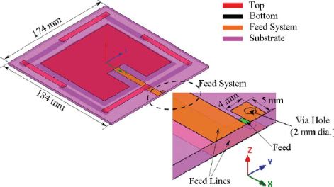
This letter presents the design of a switchable near-field (NF) and far-field (FF) reader antenna for ultra-high-frequency (UHF) radio frequency identification (RFID) applications. An overview of Ultra High Frequency (UHF) Radio-Frequency Identification (RFID) practical applications and the reader antenna design requirements are presented in this paper.
This section is written for RF coil designers and RFID system engineers. It reviews basic electromagnetic theories on antenna coils, a procedure for coil design, calculation and measurement of inductance, an antenna tuning method, and read range in RFID applications. REVIEW OF A BASIC THEORY FOR RFID ANTENNA DESIGN Current and Magnetic FieldsWhen it comes to the tag and reader antennas for the RFID, designers adopt the concept imitating the radar technology in which the re ader transmits a signal to a tag and the tag sends back its recorded data to the reader.Introduction. The ST25 NFC (near field communication) and RFID (radio frequency identification) tags extract their power from the reader field. The tag and reader antennas are inductances mutually coupled by the magnetic field, similarly to a voltage transformer (see Figure 1).
Designing an RFID antenna requires a methodical approach, starting with the selection of the operational frequency and appropriate antenna type, followed by detailed simulation and modeling to optimize its design.Antenna Matching for the TRF7960 RFID Reader. This paper describes the design method for determining an antenna matching circuit. While there are an infinite number of possible impedance matching networks, this application example focuses on a 50-Ω three element match.

This paper presents the design procedure of two ultra-high-frequency radio frequency identification reader antennas used in searching tagged items. They consist of microstrip arrays with alternating orthogonal dipoles, which are fed in series by a pairOF RFID SYSTEMS DEFINITIONS Reader, Interrogator RFID readers are used to activate passive tags with RF energy and to extract information from the tag. For this function, the reader includes RF transmission, receiving and data decoding sections. In addition, the reader often includes a serial communication (RS-232, A UHF RFID reader RF front end using an AD9361 block diagram. The AD9361 transmitter monitor path gain distribution is comprised of two gains: front-end gain (transmitter monitor gain) and receive low-pass filter gain (G BBF ).
uhf rfid reader antenna design
This letter presents the design of a switchable near-field (NF) and far-field (FF) reader antenna for ultra-high-frequency (UHF) radio frequency identification (RFID) applications.
puf korea smart card
types of rfid antenna

rfid reader antenna design procedure
could be a bit difficult to install, look for guides online and you also need other things to install .
rfid reader antenna design|high frequency rfid antenna