em18 rfid reader module pin diagram In this tutorial, we will Interface with the EM-18 RFID module using Arduino Nano, ESP8266, and ESP32 board. Overview. EM18 work on Radio frequency identification RFID is . Note: While the app will still function on devices running older versions of Android or iOS, these .Smartcard and Fingerprint Readers. State of the art readers for physical and logical access. .
0 · rfid module datasheet
1 · em18 with arduino
2 · em18 rfid reader price
3 · em18 rfid reader pinout
4 · em18 rfid reader datasheet
5 · em 18 reader module pinout
6 · em 18 reader module datasheet
7 · em 18 full form
:octocat: :credit_card: NFC Reader And Writer using Android devices by .

EM18 RFID Reader is a module which reads the ID information stored in RFID TAGS. This ID information is unique for every TAG which cannot be copied. EM-18 Pin .The Reader module comes with an on-chip antenna and can be powered up with a . In this tutorial, we will Interface with the EM-18 RFID module using Arduino Nano, ESP8266, and ESP32 board. Overview. EM18 work on Radio frequency identification RFID is .
This article describes the construction of a simple Arduino RFID Access control DIY (Do It Yourself) Project using Arduino UNO and a RFID reader module (EM-18) to control . This tutorial will show you how to quickly setup and start using the EM-18 RFID Module. Before continuing with this tutorial, watch the demo video to get a better . In this tutorial we will learn How to interface EM-18 RFID Reader Module with Arduino Uno. Connect the TX of RFID Reader to RX of Arduino for communication.EM18 RFID PIN CONFIGURATION. EM18 SPECIFICATION. RFID is an abbreviation for “ Radio-Frequency Identification ” and refers to a technology whereby digital data encoded in RFID .
Connect the GND pin of the EM18 module to a GND pin (e.g., Pin 6) on the Raspberry Pi. Connect the TX pin of the EM18 module to the RX pin (GPIO 15, Pin 10) on the .
rfid module datasheet
This RFID Reader Module works with any 125 KHz RFID tags . Specifications : 5VDC through USB (External 5V supply will boost range of the module) Current: <50mA; Operating .The Reader module comes with an on-chip antenna and can be powered up with a 5V power supply. Power-up the module and connect the transmit pin of the module to recieve pin of your . EM18 RFID Reader is a module which reads the ID information stored in RFID TAGS. This ID information is unique for every TAG which cannot be copied. EM-18 Pin Configuration. EM-18 is a nine pin device. Among nine pins, 2 pins are not connected, so we basically have to consider seven terminals.EM18 is a RFID reader which is used to read RFID tags of frequency 125 kHz. After reading tags, it transmits unique ID serially to the PC or microcontroller using UART communication or Wiegand format on respective pins.
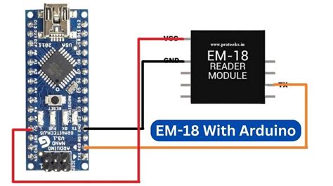
In this tutorial, we will Interface with the EM-18 RFID module using Arduino Nano, ESP8266, and ESP32 board. Overview. EM18 work on Radio frequency identification RFID is a wireless identification technology that uses Radio wave to identify the present of RFID tags.
em18 with arduino
This article describes the construction of a simple Arduino RFID Access control DIY (Do It Yourself) Project using Arduino UNO and a RFID reader module (EM-18) to control an LED and a Relay. Circuit schematic and Arduino Sketch (source code) are provided here. This tutorial will show you how to quickly setup and start using the EM-18 RFID Module. Before continuing with this tutorial, watch the demo video to get a better understanding of how the product works, and then try it yourself! What you .
In this tutorial we will learn How to interface EM-18 RFID Reader Module with Arduino Uno. Connect the TX of RFID Reader to RX of Arduino for communication.
EM18 RFID PIN CONFIGURATION. EM18 SPECIFICATION. RFID is an abbreviation for “ Radio-Frequency Identification ” and refers to a technology whereby digital data encoded in RFID tags are captured or identified by a reader via radio waves. One of the most common RFID EM18 is used with microcontrollers. Don’t worry we will see RFID SYSTEM . Connect the GND pin of the EM18 module to a GND pin (e.g., Pin 6) on the Raspberry Pi. Connect the TX pin of the EM18 module to the RX pin (GPIO 15, Pin 10) on the Raspberry Pi. Here’s a simple wiring diagram:
This RFID Reader Module works with any 125 KHz RFID tags . Specifications : 5VDC through USB (External 5V supply will boost range of the module) Current: <50mA; Operating Frequency: 125Khz; Read Distance: 10cm; Size of RFID reader module: 32mm(length) * 32mm(width) * 8mm(height) Pin Configuration of EM-18 Reader Module is shown in the figure:.The Reader module comes with an on-chip antenna and can be powered up with a 5V power supply. Power-up the module and connect the transmit pin of the module to recieve pin of your microcontroller. Show your card within the reading distance and . EM18 RFID Reader is a module which reads the ID information stored in RFID TAGS. This ID information is unique for every TAG which cannot be copied. EM-18 Pin Configuration. EM-18 is a nine pin device. Among nine pins, 2 pins are not connected, so we basically have to consider seven terminals.
lucas smart card mock test
EM18 is a RFID reader which is used to read RFID tags of frequency 125 kHz. After reading tags, it transmits unique ID serially to the PC or microcontroller using UART communication or Wiegand format on respective pins. In this tutorial, we will Interface with the EM-18 RFID module using Arduino Nano, ESP8266, and ESP32 board. Overview. EM18 work on Radio frequency identification RFID is a wireless identification technology that uses Radio wave to identify the present of RFID tags.
This article describes the construction of a simple Arduino RFID Access control DIY (Do It Yourself) Project using Arduino UNO and a RFID reader module (EM-18) to control an LED and a Relay. Circuit schematic and Arduino Sketch (source code) are provided here. This tutorial will show you how to quickly setup and start using the EM-18 RFID Module. Before continuing with this tutorial, watch the demo video to get a better understanding of how the product works, and then try it yourself! What you . In this tutorial we will learn How to interface EM-18 RFID Reader Module with Arduino Uno. Connect the TX of RFID Reader to RX of Arduino for communication.
EM18 RFID PIN CONFIGURATION. EM18 SPECIFICATION. RFID is an abbreviation for “ Radio-Frequency Identification ” and refers to a technology whereby digital data encoded in RFID tags are captured or identified by a reader via radio waves. One of the most common RFID EM18 is used with microcontrollers. Don’t worry we will see RFID SYSTEM . Connect the GND pin of the EM18 module to a GND pin (e.g., Pin 6) on the Raspberry Pi. Connect the TX pin of the EM18 module to the RX pin (GPIO 15, Pin 10) on the Raspberry Pi. Here’s a simple wiring diagram:This RFID Reader Module works with any 125 KHz RFID tags . Specifications : 5VDC through USB (External 5V supply will boost range of the module) Current: <50mA; Operating Frequency: 125Khz; Read Distance: 10cm; Size of RFID reader module: 32mm(length) * 32mm(width) * 8mm(height) Pin Configuration of EM-18 Reader Module is shown in the figure:.
lucas smart card training

em18 rfid reader price
NFC (Near Field Communication) technology is widely used for various purposes, such as contactless payments, data transfer between devices, and accessing information from .
em18 rfid reader module pin diagram|em 18 full form