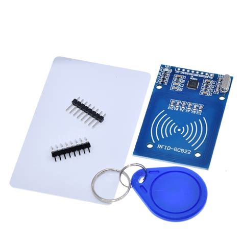
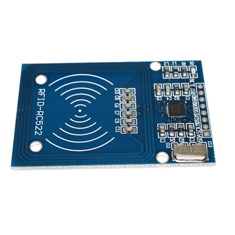
rfid reader module pin diagram An RFID or radio frequency identification system consists of two main components, a tag attached to the object to be identified, and a reader that reads the tag. A reader consists of a radio frequency module and an antenna that generates a high frequency electromagnetic field.
The Fierce Deity Link should provide the appropriate rewards, I think. I wasn't planning on doing more until the four champions. E: To clarify, we didn't know what the Amiibo was going to look like, so I paired the Majora's Mask amiibo .
0 · rfid tags and readers
1 · rfid reader module v2
2 · rfid reader module price
3 · rfid reader module pdf
4 · rfid reader module arduino
5 · rfid module price
6 · rfid module not scanning card
7 · rfid module datasheet
1. Press the + Buttom to Open the Menu. Press the + Button to open the menu, then press the R-Button to access the System Menu. 2. Go to the Options Menu and select Use amiibo. On the Options Menu, click Don't use .
RC522 RFID Module Pinout. The RC522 is a 13.56MHz RFID module that is based on the MFRC522 controller from NXP semiconductors. The module can supports I2C, SPI and UART and normally is shipped with a RFID .
EM18 RFID Reader is a module which reads the ID information stored in RFID .RC522 RFID Reader Module Pinout diagram, Pin Configuration details, Interfacing with Arduino Example, Applications, Features, Datasheet. RC522 RFID Module Pinout. The RC522 is a 13.56MHz RFID module that is based on the MFRC522 controller from NXP semiconductors. The module can supports I2C, SPI and UART and normally is shipped with a RFID card and key fob. It is commonly used in attendance systems and other person/object identification applications. EM18 RFID Reader is a module which reads the ID information stored in RFID TAGS. This ID information is unique for every TAG which cannot be copied. EM-18 Pin Configuration. EM-18 is a nine pin device. Among nine pins, 2 pins are not connected, so we basically have to consider seven terminals.
An RFID or radio frequency identification system consists of two main components, a tag attached to the object to be identified, and a reader that reads the tag. A reader consists of a radio frequency module and an antenna that generates a high frequency electromagnetic field. The RC522 module allows reading and writing RFID cards at 13.56 MHz. It is compatible with microcontrollers such as Arduino via SPI communication. Its reading range is 5 to 7 cm, ideal for access control systems. To implement security, you can integrate key or authentication systems into the tags' memory. The RC522 RFID module is one of the .

rfid tags and readers
Arduino RC522 RFID Reader Interfacing Circuit Diagram. For interfacing the RC522 RFID module with the Arduino, we will be using the SPI interface. Follow the circuit diagram and make the connections as per that. The VCC and GND pins of the module are connected to the 3.3V and GND pins of Arduino respectively.Learn how to use RFID NFC RC522 with Arduino, how to connect RFID-RC522 module to Arduino, how to code for RFID/NFC, how to program Arduino step by step. The detail instruction, code, wiring diagram, video tutorial, line-by-line code explanation are provided to help you quickly get started with Arduino. Find this and other Arduino tutorials on .We will need the following components to connect our Arduino UNO board with the RC522 module. Arduino UNO; RC522 RFID Reader module; Follow the schematic diagram below and connect them accordingly.
Hai there in this tutorial i'm going to help you with interfacing RFID-RC522 with Arduino Mega 2560 to read the RFID and Display the Data on the Serial Monitor. so you can able to extend it on your own. You Need: Arduino Mega or Arduino Uno (I used Mega) RFID-RC522; 7 male to female jumper wires; Some ID cards (optional) RFID Library (Must .Stores data onto an RFID/NFC tag. Retrieves data from an RFID/NFC tag. This tutorial focuses on: How to connect RC522 module to Arduino Nano. How to program Arduino Nano to communicate with RC522 module to read UID of RFID tag.RC522 RFID Reader Module Pinout diagram, Pin Configuration details, Interfacing with Arduino Example, Applications, Features, Datasheet. RC522 RFID Module Pinout. The RC522 is a 13.56MHz RFID module that is based on the MFRC522 controller from NXP semiconductors. The module can supports I2C, SPI and UART and normally is shipped with a RFID card and key fob. It is commonly used in attendance systems and other person/object identification applications.
EM18 RFID Reader is a module which reads the ID information stored in RFID TAGS. This ID information is unique for every TAG which cannot be copied. EM-18 Pin Configuration. EM-18 is a nine pin device. Among nine pins, 2 pins are not connected, so we basically have to consider seven terminals.
An RFID or radio frequency identification system consists of two main components, a tag attached to the object to be identified, and a reader that reads the tag. A reader consists of a radio frequency module and an antenna that generates a high frequency electromagnetic field. The RC522 module allows reading and writing RFID cards at 13.56 MHz. It is compatible with microcontrollers such as Arduino via SPI communication. Its reading range is 5 to 7 cm, ideal for access control systems. To implement security, you can integrate key or authentication systems into the tags' memory. The RC522 RFID module is one of the . Arduino RC522 RFID Reader Interfacing Circuit Diagram. For interfacing the RC522 RFID module with the Arduino, we will be using the SPI interface. Follow the circuit diagram and make the connections as per that. The VCC and GND pins of the module are connected to the 3.3V and GND pins of Arduino respectively.Learn how to use RFID NFC RC522 with Arduino, how to connect RFID-RC522 module to Arduino, how to code for RFID/NFC, how to program Arduino step by step. The detail instruction, code, wiring diagram, video tutorial, line-by-line code explanation are provided to help you quickly get started with Arduino. Find this and other Arduino tutorials on .
We will need the following components to connect our Arduino UNO board with the RC522 module. Arduino UNO; RC522 RFID Reader module; Follow the schematic diagram below and connect them accordingly.Hai there in this tutorial i'm going to help you with interfacing RFID-RC522 with Arduino Mega 2560 to read the RFID and Display the Data on the Serial Monitor. so you can able to extend it on your own. You Need: Arduino Mega or Arduino Uno (I used Mega) RFID-RC522; 7 male to female jumper wires; Some ID cards (optional) RFID Library (Must .

rfid reader module v2
Load NFC Cards: Place the NFC cards into the printer’s input tray or designated card slot. Make sure that the cards are correctly aligned and securely positioned to avoid any printing errors or misalignments. 4. Set .
rfid reader module pin diagram|rfid tags and readers